This chapter is composed of :
The purpose of this chapter is to show how to generate a Database Diagram.
Depending on the Database Connection UML Diagram you can create as many diagrams as you like.
To start the Database Diagram wizard, select :
File->New->Other->Database->Database Diagram
or
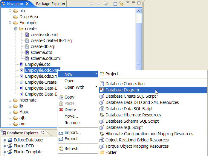
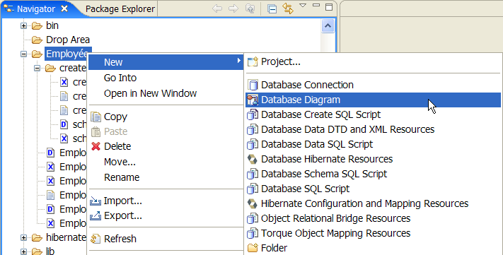
Select an object in the Package Explorer View or the Navigator View then right-click and select :
New->Other->Database->Database Diagram
The selection is contextual.This means that if you select an existing Database Object :

The wizard will open the parent Database Connection in update mode.
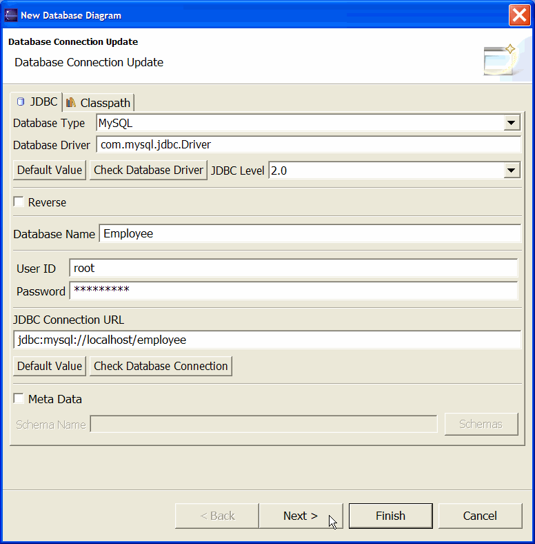
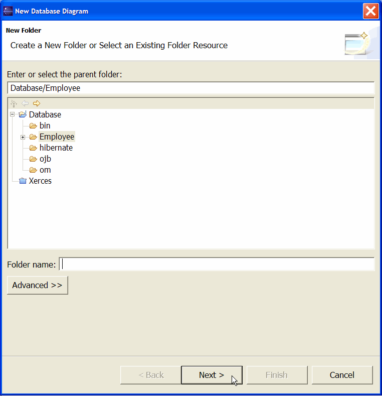
Otherwise :
A new Database Connection wizard will be opened starting with a New Folder selector.
In Database Connection Update mode this wizard has four pages :
In Database Connection Create mode this wizard has five pages :
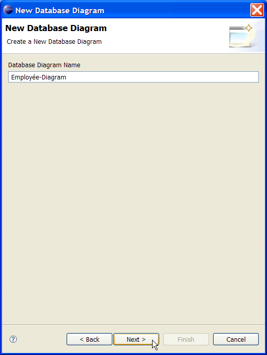
Database Diagram Name is the name of your new diagram.
Each resource should have a unique name in the targeted selected workspace folder or project root.
This data is not related to any Meta Data informations.
This name will be the file name of the generated Diagram file.
A Database Diagram is an XML file, its file extension could be :
This file extension is managed by the Save Policy Preference.
This file is referenced in your current Database Connection.
The new Database Diagram will be created.
The Diagram will be opened in its editor and a Schema selector will be proposed.

Once you select the Tables you are interested in, the Diagram will display these objects.
